We use cookies to make your experience better. To comply with the new e-Privacy directive, we need to ask for your consent to set the cookies. Learn more.

How to Refine an Unstructured Grid
When working with a multi-layer unstructured grid (UGrid) in the Ground-water Modeling System (GMS), your project may require different levels of refinement in each layer to introduce complexity to the stratigraphy. GMS currently offers a limited number of ways to achieve this in a 3D UGrid module. Mapping coverage directly to a 3D grid simplifies vertical refinement considerably, but it results in all layers being of uniform size. This blog post will cover the most straightforward way to create a complex stratigraphy, as well as some things that may be useful to know about how refining grids works and what the limitations are.
The type of grid that will often get you the closest to where you want to be is a Quadtree grid. These are the steps you’ll want to follow:
- Use the TINs/Horizons to UGrid approach to generate a grid that incorporates the desired pinchouts and ensures an appropriate level of refinement for the least refined layer.
- Right-click on the Quadtree UGrid in the Project Explorer and scroll to the bottom of the UGrid Properties dialog window.
- Make sure the Constraint dropdown is set to "None". If the constraint is set to "3D", you will not be able to refine the UGrid cells. Note that you can’t change the constraint back to "3D" after changing to "None", so you may want to duplicate the UGrid and make changes to that one to preserve the original.
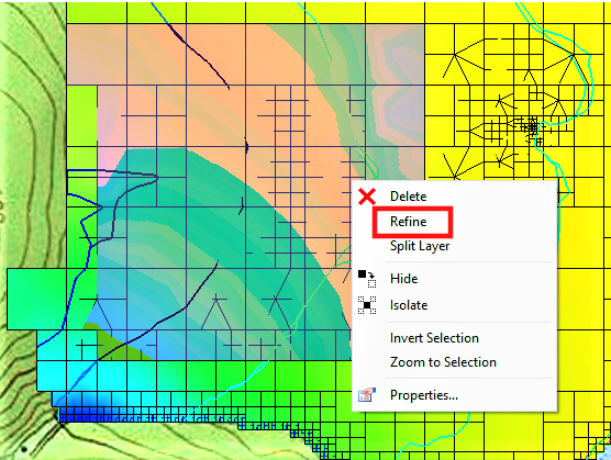
- In the toolbar above the Graphics Window, check the box for Single Layer to isolate a layer of the grid for refinement. Highlight the cells you wish to refine using the Select Cells tool.
- Right-click on the selected cells and choose Refine.
The newly generated UGrid maintains the original level of refinement on all layers except for the one where you just refined some of the cells. You can repeat this process as many times as needed to achieve the desired level of refinement.
Currently, there is no automated process for this kind of complex refinement, so while it is possible to use this process on a larger project, it may not be practical. If you have a limited number of areas to work on, this workflow lets you produce a grid that features your desired TIN pinchouts, with varying levels of refinement for different layers. It is also not possible to un-refine a grid, so you’ll always need to start with the least refined layer and work your way to the most refined.
Head over to GMS and try this method to refine your 3D grid today!
October 3, 2023
|
View: 2909
|
Categories: GMS
|
By: <a class="mp-info" href="https://aquaveo.com/blog/author/admin">Aquaveo Staff</a>
About the Author

Performing a Silent Install of XMS (Passwords & Hardware Locks)
October 10, 2018
Computing Basin Curve Numbers in 9 Easy Steps
May 16, 2023
Converting a NET File to an INP File
May 9, 2018
Performing a Silent Install for ALS
October 27, 2021
Tips for Finding Information on the XMS Wiki
September 25, 2019
Managing MODFLOW 6 Data: Lists, Copy Period & CSVs
April 21, 2026
5 Concepts for Mastering Surface-water Modeling
April 14, 2026
Comparing Multiple Design Alternatives in One Project
April 7, 2026
Incorporating MODFLOW 6 Groundwater Energy (GWE)
March 31, 2026
Essential DEM Clean-Up for Watershed Delineation
March 24, 2026