Aquaveo & Water Resources Engineering News

6 Ways to Select 3D Cells

When using a 3D grid in GMS, it’s likely you will need to select a grid cell at some point in the project. This is usually a straightforward procedure. However, sometimes the 3D nature of the grid makes it less obvious as to which cells are selected.

To cover the basics of selecting cells, here are six ways to select 3D grid cells in GMS.

1. Select Cells Tool

The Select Cells tool is the most obvious choice and the tool most often used to select cells in a 3D grid. The tool can be used to select multiple cells by clicking and dragging a box over a group of cells. Multiple cells can be selected by using using the Shift or Ctrl keys. Select one cell, hold down the Shift key, and select a second cell to select both cells and all the cells in between. If you want to select cells without getting all the cells in between, use the Ctrl key.

Using the Select Cells tool only selects the visible cells, so be certain you are on the correct layer of your 3D grid. It will not select the cells underneath.

2. Select i, Select j, and Select k Tools

These tools are a lot like the Select Cells tool and operate in a similar way. The only difference is these tools will select entire rows or even entire layers. These tools depend on the view you are in and the layer being shown.

For example, if using the Select i tool, one or more rows can be select when in plan view. Only rows on the visible layer will be selected. When switching to a front view, the Select i tool will select all visible cells because all of the cells are active in the i direction of the 3D grid.

Unlike the Select Cells tool, the Shift key functions like the Ctrl key when selecting multiple rows of cells.

3. Select All

This tool does what it says. The Select All command under the Edit menu, will select all visible cells in the 3D grid. If the view is changed (e.g., from front view to plan view), all cells will be deselected. This command can also be accessed by pressing Ctrl+A on your keyboard.

4. Select With Poly

Dragging a box over a group of cells is nice, but sometimes you need a little more precision. Using the Select With Poly command in the Edit menu will let you click out a polygon shape to define your selection area. Double-clicking ends the process and reverts back to whatever tool you had previously selected.
5. Select By ID

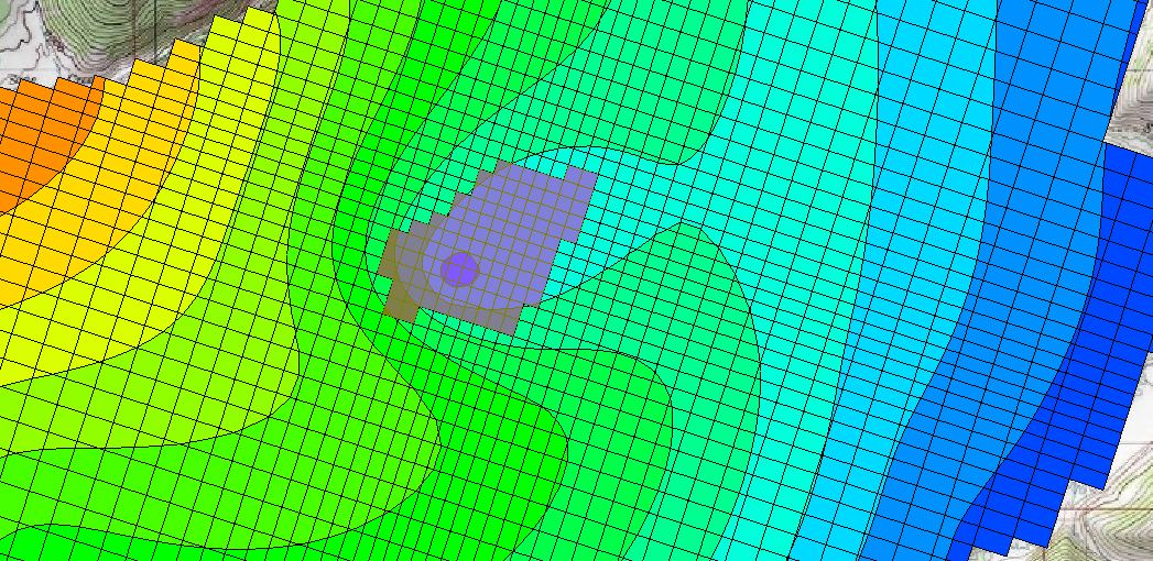
Do you have a specific cell you want to select, for example the location of a well or perhaps you received an error message about a cell when running a model check? If you know the cell ID or the location, you can use the Select By ID command under the Edit menu. This brings up the Find Grid Cell dialog where you can enter the cell ID or location. When done, you’ll find the cell has been selected. This tool does require that the cell be visible in the Graphics Window.

6. Select By Dataset Value

Sometimes there is a range of cells you’d like to select which contain a specific set of values. This can be done by using the Select By Dataset Value command in the Edit menu. Be certain the dataset with the values you want to select is active before using this command. It will bring up the Select by Dataset Value dialog where you can specify selecting cells with a certain value range.

There are other ways to select cells in GMS, but these are the most common methods. Check out the selection options for 3D grids in GMS today!
Blog tags: 

How to Use TauDEM in WMS to Define Flow Paths

Using a watershed delineation tool is one of the first steps in creating a usable model for any sort of watershed, whether for conservation of natural resources, further development of a municipal drainage system, or determining potential flood zones. Tools such as TauDEM can make the process much simpler by basing those calculations off an existing DEM.

The process is generally straightforward:

  1. Import a DEM for the area in question.

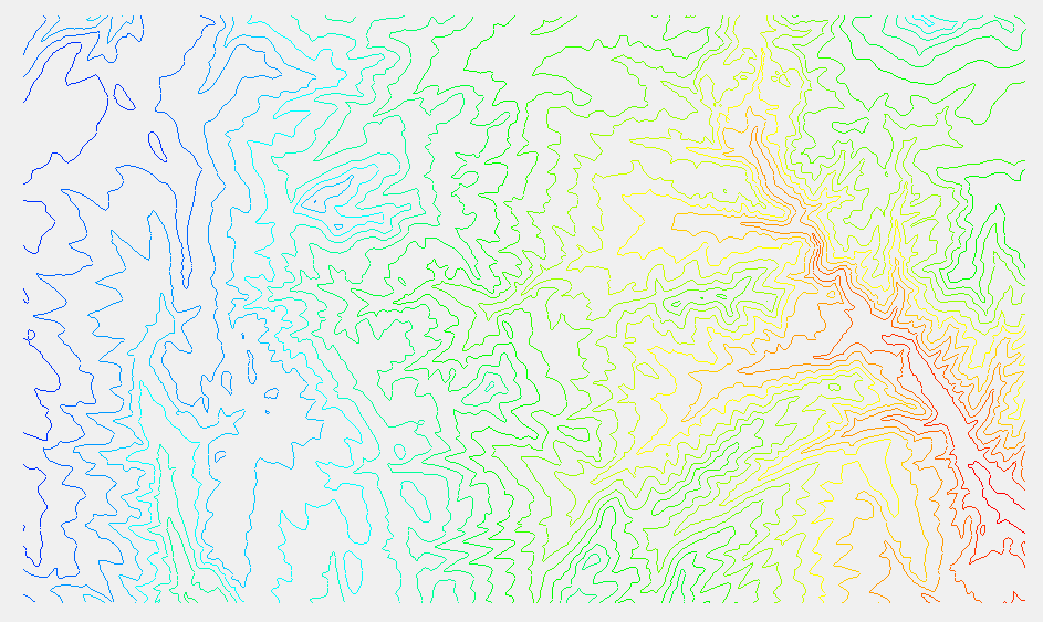
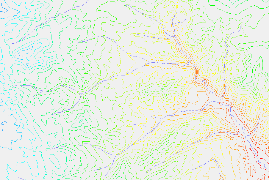
    DEMs can be obtained many different ways. They can be imported directly using the features in WMS, they can be downloaded for free from the USGS and other governmental sites, or they can be created by you using lidar or similar tools. This is the DEM used in this example:

  2. Once the DEM is imported, activate the Drainage module.
  3. Select DEM | Compute Flow Direction/Accumulation... to bring up the Flow Direction/Accumulation Run Options dialog.
  4. Select Run TauDEM under Select the model to determine the flow direction/accumulation.
  5. If you want to use multiple processors, check the box next to Use MPICH2 and enter the number of processors.

    If you don’t know if your computer has multiple processors, simply leave the box unchecked.

  6. If this is your first time running MPICH2, click Register MPIEXEC and enter your username and password at the prompt. This should be your Windows username and password.
  7. Click OK to close the Flow Direction/Accumulation Run Options dialog and bring up the Units dialog.
  8. Set the units to be appropriate for the location of the project and click OK.

    The watershed delineation process can take some time, depending on the size of the area being delineated and the computer being used. Once TauDEM has finished delineation, the cells accumulating the flow will appear.

  9. When TauDEM is finished running, click Close to exit the Model Wrapper dialog.

TauDEM is part of the Community Edition of WMS, so you can try out this feature today.

Blog tags: 

How to Make an Unstructured Floodplain Mesh

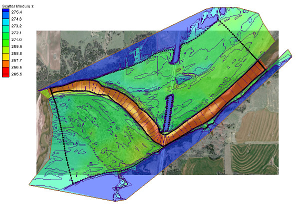
Flooding can cause significant--and sometimes devastating--damage to infrastructure, crops, and commercial, residential, and industrial buildings. Unstructured floodplain meshes can be used to anticipate the most likely scenarios and plan prevention and mitigation accordingly. These are only some of the reasons why an unstructured floodplain mesh might need to be created. Your project may include multiple low lying areas that historically flood. You may need to see where berms or channels need to be adjusted to better accommodate sudden flow increases and prevent or mitigate flooding.

There are a few steps that should be taken anytime you model and simulate an unstructured floodplain mesh. SMS simplifies this process.

1. Import Background Data

The first step is usually to import elevation data from a scatterpoint dataset, raster objects, lidar data, mesh, grid, or from an existing project that includes the required elevation information for the floodplain. If the elevation data is not from a scatter set, it will need to be converted to a scatter set or interpolated to the mesh after the mesh is generated.

An aerial photo of the area can also be imported to help with visually referencing rivers, roads, and other structures.

2. Create a Mesh Generator Coverage

Once the elevation data has been imported, create a mesh generator coverage by right-clicking in the Project Explorer and selecting the New Coverage command. From the New Coverage dialog, select the Mesh Coverage type and enter a name for the coverage.

3. Create Feature Objects

The unstructured floodplain mesh will be generated from polygons in the mesh generator coverage. On the mesh generator coverage, create the enclosed arcs encompassing the area of the floodplain using the Create Feature Arc tool. Turn the enclosed arcs into a polygons by using the Build Polygons command.

4. Assign Mesh Type and Bathymetry

Use the Select Feature Polygon tool to double-click on each of your polygons. In the dialog that appears, assign the mesh type you want to create. You can use the Preview Mesh button to ensure your mesh will generate correctly.

After selecting the mesh type, select constant value or scatter set to use as the mesh elevation.

Once this is done for all your polygons, you are ready to generate your unstructured floodplain mesh.

5. Generate the Unstructured Floodplain Mesh

The process of generating your mesh is quite simple if the above processes are followed. Simply right-click on the mesh generator coverage and select the Convert to 2D Mesh command. SMS will start the calculations to create the mesh. Older versions of the software will bring up an options dialog where a few changes can be made to how the mesh is generated. For most projects, the default options are acceptable. A dialog will then appear asking you to name your mesh—the final step in creating the mesh.

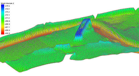
Now you have an unstructured floodplain mesh. Explore the mesh to see if you like the results and get started on the rest of your project. You can adjust the display options at this point to make sure your mesh is satisfactory.

You can try out creating unstructured floodplain mesh generation in the SMS Community Edition for free.

Blog tags: