Aquaveo & Water Resources Engineering News

Sharing GMS Project Files

As many of us work in a collaborative environment, sharing projects becomes essential. When sharing a GMS project, it is not as simple as sending over just the GMS project group file (*.gpr) project file. GMS projects are stored in multiple separate files that work together. When sharing a GMS project, it is important to include all of the necessary files.

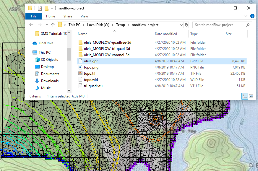
GMS projects are saved as a project group file (*.gpr). This file saves feature objects, projection data, data objects and other general settings. However, it only references many other aspects of a project that are contained in separate files. It will reference the location of all external files such as shapefiles (*.shp, *.dbf, *.prj, etc.), images, CAD files, grid files, etc. When sharing a GPR file, the file needs to be able to locate these external files. Ideally, these files should be located in the same folder as the GPR file. This is why it is recommended to zip all the project files together before you send it out to be shared.

GMS project files

When your project contains a MODFLOW model, it is important to know that GMS saves the MODFLOW project in separate files. For example, each package saved as a different file. Rivers (*.riv), drains (*.drn), wells (*.wel), streams (*.str), recharge (.rch), etc. are all different packages with different file extensions. Sending over just the package file, such as only sending a wells file, is not much use as GMS will likely be unable to open it.

Along with the MODFLOW package files, GMS will need the MODFLOW name file (*.mfn). This file allows GMS to build the MODFLOW project when it is imported. All other input and output MODFLOW files should be included when sharing your GMS project.

Note that many files will be saved in a folder created next to the GPR file. Files in the folder should be left there and the entire folder should be moved with the GPR file. GMS saves the relative location of files included in the project.

When sharing your GMS project, keeping all of the necessary files together can save the person receiving the project a lot of frustration. For more about GMS file formats, be sure to check out the GMS articles on the XMSWiki and start sharing your GMS projects today!

Blog tags: 

Exporting a High-Resolution Plot

While working in WMS, you may need to export a profile plot or hydrograph at a high resolution. This can be particularly useful when preparing a presentation or sending the results of your project for publication. Having a high resolution plot allows presenting your work at its best. This blog post is meant to show you how to export a high-resolution profile plot in WMS.

The needed resolution of the plot or hydrograph will vary depending on the final output. Resolution for screens and powerpoint presentations does not need to be as high as for print publications. By default, WMS uses a lower resolution for hydrographs and plots to conserve computer processing power. When exporting, higher resolutions can be specified.

In order to export a high resolution plot, a profile plot or hydrograph needs to be created. After generating the profile plot or hydrograph, the below steps will show how to export it with a high resolution.

  1. Right-click on the plot window and select Export/Print.
  2. In the Exporting Profile dialog, select which file type to export and where to save the file.
  3. At the bottom of the dialog, there is an option to set the size and resolution of the file to make it a higher quality image.
Exporting a plot

Remember that, in changing the size of an image, there are limits to how large the image can be. Each image should be scaled to accurately fit within its limited dimensions.

It is recommended to check the export plot file after exporting. It is recommended to open the exported plot file in software outside of WMS to check the resolution. Also review the final file size before sending it. If there is a discrepancy, adjust the export settings in WMS and try again.

Try out exporting your plots and hydrographs from WMS today!

Blog tags: 

Converting Mesh Data to a Raster

After creating a mesh in SMS, you may want to share the data in the mesh as a raster file. For example, you might want to convert the water elevation or velocity dataset from a model run into a raster. Raster files can be opened by many programs and can contain a lot of useful information.

While a raster cannot be created directly from the Mesh module, it can be created from other modules, so the mesh data will need to be converted. To do this:

  1. In the Project Explorer, select the mesh you want to convert to a raster.
  2. Right-click and select Convert | Mesh to 2D Scatter.
  3. In the Convert Mesh to Scatter Points dialog, use the Convert only corner nodes option and give the scatter set a name.

After the mesh has been converted to a scatter set, a couple more things have to be done. The datasets, except for the elevation set, will need to then be interpolated over to the scatter set.

  1. In the Project Explorer, right-click on the mesh and select Interpolate to command.
  2. In the Interpolation Options dialog, select the datasets to interpolate over to the scatter set generated from the Mesh.

Once the mesh and datasets have been converted to the Scatter module, they can be converted to a raster by doing the following:

  1. Select the dataset and time step to be converted.
  2. In the Project Explorer, right-click and select Convert | Scatter to Raster.
  3. Select raster options in the Interpolate Scatter to Raster dialog.
  4. Give the raster a file name and save it as a GeoTIFF.

When going through this process, the active dataset and the active time step at the time of the conversion will be the information saved to the GeoTIFF file.

Mesh data to raster

Feel free to try out the above process of converting a mesh dataset to a raster file in SMS today!

Blog tags: 

Tips for Exporting a MODPATH Project

MODPATH works with MODFLOW to show particle tracking information. Once you have successfully completed a MODFLOW project, you may want to share that information collected through MODPATH with your other colleagues. Exporting the MODPATH data can allow you to share specific information with them.

Typically, the Save As command in the File menu and the right-click Export command in the Project Explorer are used to export MODPATH data from GMS. When using these commands, there are some tips for getting the most out of them.

Exportin MODFLOW
Exporting MODPATH Flowlines to a KMZ File

The flowlines from a successful MODPATH run can be exported as a KMZ file using the Save As command. When doing this, pay attention to the following:

  • Use the Display Options to make the flowline more visible before exporting to a KMZ file.
  • Make certain that the projection/coordinate system of your MODPATH project has been set correctly. KMZ files require that a coordinate system be set therefore GMS cannot create a file if there is no projection.
  • Objects in the Project Explorer can be set to different projections. Be certain to review the projections of all objects when exporting a KMZ file.
Exporting Points

Using the Save As command, the particle points of the MODPATH project can be exported to a shapefile.

  • When exporting particle points from MODPATH it is important to note that endpoints will need to be exported with intermediate points.
  • Another option is to use the Text Tab Delimited Pathline File option, which prints out the location and could be quickly parsed to pull the X and Y locations for the last time step of each particle.
  • MODPATH output can be exported to a shapefile or text delimited file by right-clicking on your MODPATH particle set in the Project Explorer and selecting "Export".
  • In the "Export Particle Sets" dialog that comes up, you can then change the "Save as type" option at the bottom to the type (pathlines, points, vectors), and format (shapefile, text delimited file) you prefer.

Many of these tips apply to exporting other numeric modeling data in GMS. Try out the different export functionalities in GMS today!

Blog tags: 

Obtaining DEM and TIN Data in WMS

For many watershed modeling projects, having the correct DEM or TIN can make a huge difference. Importing a DEM or TIN into WMS can be done in any of a few ways.

The easiest way to obtain a DEM or TIN is to import a file from your computer directly into your project. This can be done using any of the methods for opening a file: the Open command, drag-and-drop, etc.

Once your DEM or TIN file is in WMS, check to make certain it is in the correct module. In order for WMS to make use of DEM or TIN, it often needs to be in the Terrain Data module. Sometimes, a DEM or TIN will be imported as a raster file or scatter set. In order to fix this, the DEM or TIN needs to be converted.

  • When imported as a raster file, right-click on the raster file in the Project Explorer and select Convert To | DEM. Then select the resample size for the DEM.
  • When imported as a scatter set, right-click on the scatter set in the Project Explorer and select Convert | Scatter Points to TIN.

Once the data has been moved to the Terrain Data module, it can be moved from a TIN to DEM or a DEM to TIN as needed. This is done by right-clicking on the DEM or TIN and using the Convert commands.

Converting a DEM to a TIN

Knowing how to convert data to be either a DEM or TIN in the Terrain Data module allows you to make use of the Import from Web and Online Maps functions in WMS to obtain DEMs and TINs. Other data sources can be used, when available.

A DEM can also be obtained when using the Hydrologic Modeling Wizard. In the Download Data step, elevation data can be downloaded that will automatically be placed in the Terrain Data module as a DEM.

Make use of DEMs and TINs in your watershed modeling using WMS today!

Blog tags: