Aquaveo & Water Resources Engineering News

Performing a Silent Install for ALS

Are you an IT administrator needing to perform a silent install of GMS, SMS, or WMS in a classroom or office? We have gone over the process to do this in the past. However, our licensing methods have changed since those instructions were first written. Because of this, we have felt it would be useful to update our users on the new method of configuration so they will be able to properly set up their silent installs. This post will review registration for the new licensing method and how to perform silent installs with it.

This silent install (or quiet install) workaround requires each user to have the rights to modify the registry. If registry access is restricted, a network administrator can do this by opening the Group Policy Management Editor and creating a startup script that automatically runs the batch file whenever the computer is restarted.

Note: Editing the Registry in Windows is a very advanced administration step. Please always create a backup of the Registry before making changes.

It can be a burden to manually update the local code in HKEY_CURRENT_USER for each user on each computer. The silent install process is simplified by creating a Windows Registry file that contains the license information and a batch file that can be executed to insert the registry information and launch WMS. The batch file automatically updates the registry for the user and then opens the WMS application. This is the safest way to edit the registry key, as well. The batch file can then be placed on each computer that needs to be updated, and the individual users can execute it as needed.

This workaround uses WMS as an example. This information also applies to GMS and SMS. You can see an example of a registry file in step 1 and the batch file in step 2, below.

  1. Create a file, "Netenble.001.reg", as follows:
    Windows Registry Editor Version 5.00M
    "ALS"="1"
    "ALSHost"="127.0.0.1"
    "ALSPort"="56789"

    ALS = 1 specifies the new registration wizard, with new "Local" codes beginning with L, F, or E, instead of 0 for the old network lock. ALSHost = 127.0.0.1 because the code is being located on the local machine. And ALSPort = 56789 should be the default - you can alternatively specify your own port if you would like. You could also specify an ALSCode (license code) as well if you don’t want registration to be required when first launching WMS.
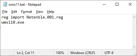
    Note: This information was created using Windows 10. Because different Windows versions can have different REG file formats, we recommend you install WMS on one machine, register it to the correct local code, then export the registry key. Open the registry file in the text editor and remove every line except those similar to those shown in the image above, and save the file as "Netenble.001.reg".
  2. Create a file, "wms11.bat", that will update the registry and start WMS:
    reg import Netenble.001.reg
    wms.exe
  3. Place these two files in the WMS folder in the image that will be distributed to the affected computers. For example, for the 64-bit version of WMS 11.1, the default location for the folder is “C:\Program Files\WMS 11.1 64-bit\”.
  4. Create a desktop shortcut to the batch file for the convenience of the user. If doing this via a startup script in the Group Policy Management Editor, this step can be skipped.

This silent install workaround can save you significant time as a network administrator. If you experience issues while performing a silent install, feel free to contact Aquaveo for assistance.

Associating HY-8 Files with SMS

Have you wondered about how HY-8 interacts with SRH-2D in SMS? This post will review what HY-8 and SRH-2D are doing as they interact with each other.

SRH-2D has an option to use the HY-8 software to define culverts. Using the HY-8 software allows for greater definition for the culvert as opposed to defining the culvert directly in SMS. The Launch HY-8 button in the SRH-2D Assign BC dialog creates the HY-8 file and associates the file with the culvert arcs and SMS project. It is important to keep this file with the SMS project, otherwise the HY-8 file may become unassociated with the culvert.

Multiple culverts can be in the same HY-8 file, so be certain the correct culvert has been associated to the culvert arcs in SMS.

SRH-2D culvert using HY-8

When assigning properties to arcs that have been set to a BC Type of Culvert HY-8, there is a checkbox option to turn on 2D terrain for overtopping. When this is unchecked, SRH-2D will create a *_HYn.dat for the crossing. When this is checked, SRH-2D will instead create an *_INTERNALn.dat file for the crossing. In this case, SRH-2D will use the HY-8 table, but won’t see the structure as a HY-8 culvert, but as essentially a link structure.

Typically, the overtopping option is used when overtopping flow is expected to travel in a different direction from the rest of the flow. If the flow over the culvert and the flow in the culvert are both flowing in the same direction, it is not recommended to use 2D Overtopping. This is because the link structure in SRH-2D can get flow from both upstream and downstream of the boundary arc and the flow coming out of the downstream arc can go in any direction.

When SRH-2D runs, it will generate output files that are sent to an Output_MISC folder in the file directory of your current SMS project. Here, HY-8 culvert report files and/or pressure flow overtopping report files should be found, following the respective naming schemes of “*_HYn.dat” and “*_INTERNALn.dat”. The “*” is a placeholder for the specific case name specified in the model control, and the “n” will be replaced with a number in a series, for as many relevant zones or arc pairs exist in the series. We unfortunately don’t have any control over the naming convention SRH-2D uses.

More information about the different types of SRH-2D output files that may be put out after an SRH-2D run can be found here at the Aquaveo XMS Wiki.

Try out using HY-8 with SRH-2D in SMS 13.1 today!

Blog tags: 

Incorporating Transport Observation Points into a MT3DMS Model

Have you wanted to incorporate the TOB package while running MT3DMS in GMS? We have a workflow that can help with this, as part of building an MT3DMS model in GMS with a conceptual model approach. This post will review how to incorporate transport observation points into your MT3DMS model in GMS.

To do so, use the following steps:

Transport Observatin Package
  1. With your MT3DMS model already open in GMS, right-click the conceptual model and select New Coverage... to create a new coverage and bring up the Coverage Setup dialog.
  2. While in the Coverage Setup dialog, turn on whichever options you want to be observing for in the Obs. Data column of the Observation Points section.
  3. Once done with the Coverage Setup dialog and with a new coverage created, create some points within the coverage.
  4. Using the Select Points\Nodes tool, select the points you have just created, right-click on one of them, and select Attribute Table… to bring up the Attribute Table dialog.
  5. Set the Type drop-down in the All row to obs. pt in the Attribute Table dialog to set the BC type to Observation Points for the points.
  6. Once done with the Attribute Table dialog and with the points set as observation points, right-click the new coverage and select Map To | MODFLOW/MODPATH to map the new coverage to MODFLOW.
  7. Now select MT3DMS | Basic Transport Package… to bring up the Basic Transport Package dialog.
  8. Select the Packages... button to bring up the MT3DMS/RT3D Packages dialog.
  9. Turn on the option for Transport observation package.
  10. Now select MT3DMS | Transport Observation Package... to bring up the Transport Observation Package dialog.
  11. Now you will have the ability to turn on the option to Compute concentrations at observation points and select coverages with concentration observations to be used.

Try out incorporating transport observation points into MT3DMS models in GMS 10.5 today!

Blog tags: 

Tips for Using the Measure Tool in WMS

Have you used the Measure tool in WMS? You probably have, but would you like to know more about the tools capabilities? This post will review the capabilities of the Measure tool and give some tips for using it.

The Measure tool allows you to measure distance, slope, and in some cases angles along a path you define. It is designed to give you real-world measurement sizes, and can be useful when the scale of parts of a model aren't immediately apparent. When the tool is selected, you will be able to define a series of line segments along a path. This path can be continually defined until it is terminated by double-clicking. When the path is terminated, it will disappear from the Graphics Window, but along the bottom of WMS, in the Help Message window, the relevant values will be displayed in red text. These will be updated whenever the Measure tool is used, reflecting the most recent path that was defined.

Example of using the Measure tool

The units for distance and slope will depend on the units set by the projection, or by the project defaults, either ft and ft/ft (feet) or m and m/m (meters). It is recommended to make certain you have set the correct units for your project before using the Measure tool.

Angle will only be reported when a line only has two points, whereas distance and slope are always reported. Angle will be measured in radians. Angle will be calculated by measuring an angle starting from a reference line pointing south from the first point, and ending at the line segment defined by the two points.

If you have a TIN or DEM loaded into the project, the Measure tool will be able to get slope values. When the Measure tool is used on an area without elevation data, the slope will be given a value of zero. Slope will be calculated by taking the distance-weighted average of the slopes of all the segments. For each segment, slope will be calculated by dividing the change in elevation across the points by the xy distance of the segment.

The Measure tool can help you build and design your project with accuracy. Try out the Measure tool in WMS 11.1 today!

Blog tags: