Moving Data to Other Geometries
By aquaveo on April 30, 2024After you have created a model in the Surface-water Modeling System (SMS), it is not uncommon to need to move your vector data or solution datasets from one geometry to another. It could be that your model ran using a 2D mesh and now you want to move the vector data to an unstructured grid for use in another simulation. SMS gives you the ability to accurately move vector data from one geometry to another which can significantly enhance the precision of your modeling efforts.
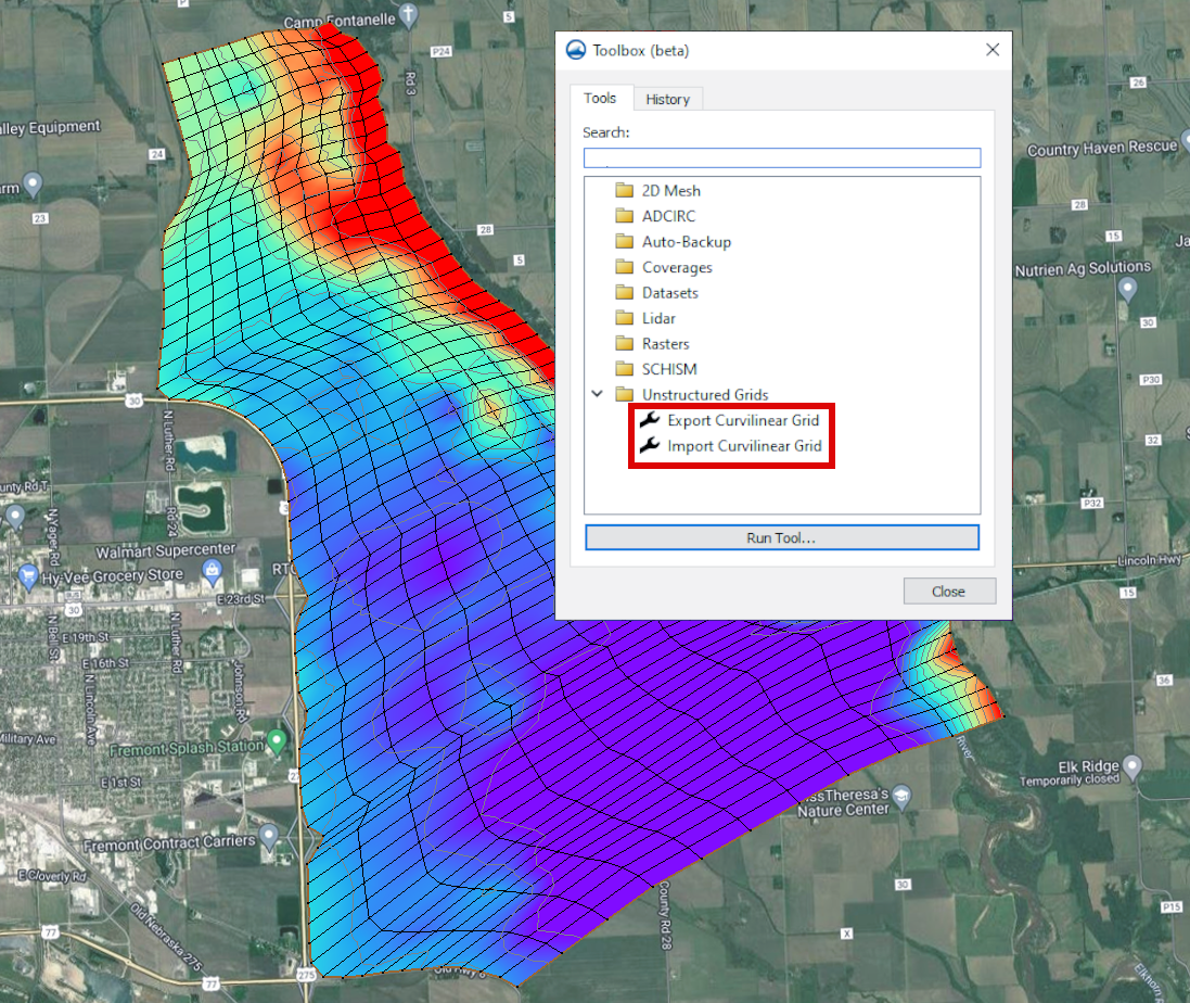
The Interpolate to UGrid tool is a powerful feature designed to streamline this process of moving datasets from one geometry to another. The Interpolate to UGrid tool is located in the Toolbox with the suite of dataset tools.
The Interpolate to UGrid tool facilitates the interpolation of a dataset associated with one geometry to another within the same project. While it primarily is meant to work with unstructured grids (UGrids), it can be used with other geometries such as 2D meshes or Cartesian grids. The tool will accept any dataset on the geometry, including vector and elevation sets.
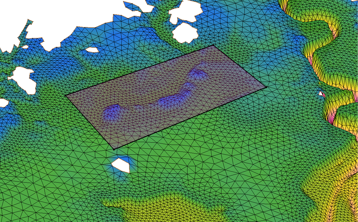
The tool will follow an interpolation process to assign values on nodes or cells from one geometry to the next. Because of this, it is important to review the dataset after it has been moved, to verify that it transferred as expected.
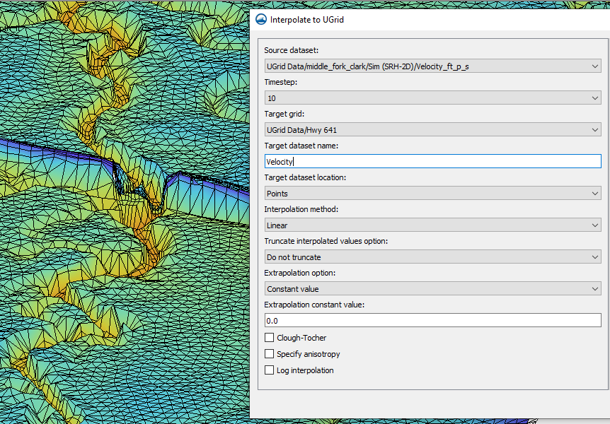
The Interpolate to UGrid tool gives you several features that let you control the process of moving data from one geometry to another. These include:
- Versatile Interpolation Methods: Choose the interpolation method that best suits your data and modeling objectives to achieve optimal results.
- Customizable Interpolation Dimension: Tailor the interpolation process to match the dimensions of your target grid, whether it's 2D or 3D.
- Truncation Options: Control the range of interpolated values with flexible truncation options. Whether you want to preserve the original data range or define custom minimum and maximum values, this tool provides the flexibility you need to fine-tune your results.
- Extrapolation Capabilities: Handle extrapolation scenarios with ease, choosing from various extrapolation options to extend your dataset beyond the convex hull of the scatter point set.
Whether you're working with unstructured grids, 2D meshes, or other geometric entities, this tool provides the functionality and flexibility you need to enhance the accuracy of your modeling efforts. Make use of the Interpolate to UGrid tool in your SMS projects today!