Aquaveo & Water Resources Engineering News

Working with Units in GMS

For any groundwater modeling project, having the correct units is essential in creating a valid project. When working with GMS, make certain that the project units are correct. To help you with having the correct units, here are some tips for working with units in GMS.

Check Input Units

Before importing data into GMS, check units of the data. Ideally, all of your data will be using the same units. So, for example, if you are working in meters then make certain all the data you will be importing is in meters.

It is recommended that you convert the data into the correct units before importing it into GMS. GMS will not change the units of your data during the import process. That said, it is recommended to check the units of imported data to make certain the data imported correctly. This is done by checking the data’s projection.

Please note that GMS also does not perform unit conversions when writing values to input files for models, such as MODFLOW or MT3DMS packages, but writes the values to input files as they are shown in their respective package dialogs.

Converting Units

Instead of converting the units of your data before importing it into GMS, you can convert some data inside GMS. GMS does not do automatic conversion of units for data. So if all of your data is in meters and you bring in one set of data that is in feet, GMS will not automatically convert the data from feet to meters.

Instead, after importing the data, you have two options for converting the data into the correct units.

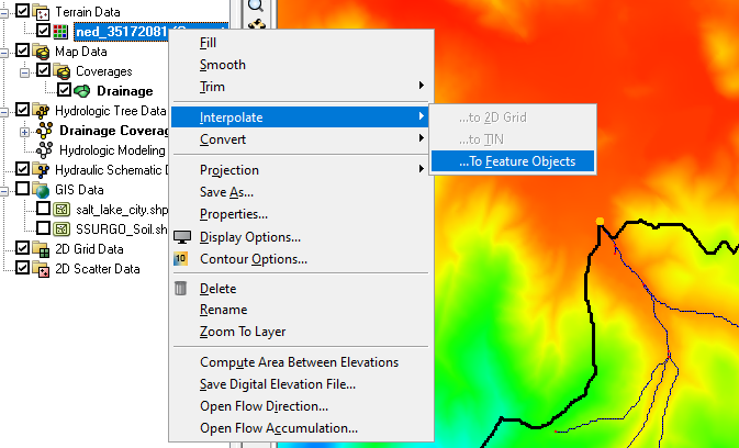
The first of these options is to reproject the data. This is done by right-clicking on the data in the Project Explorer and selecting the Reproject command. This option can quickly change the units of the data in GMS.

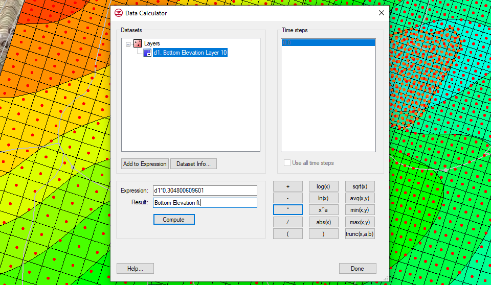
The other option is to create a new dataset with the correct units. This is done using the Data Calculator. In the Data Calculator, you would select the dataset with the wrong units then enter the equation to convert the dataset units into the calculator. Once the new dataset is calculated, make certain that dataset is being used in the project and not the older dataset.

Using the Data Calculator to convert units
Check Output Units

After completing your model and running it, it is recommended that you check the units of the output data. In most cases, the units in the output data will be correct. If the units are not correct, this often indicates an issue with the input values of the model. GMS does not change the units of data during the model run.

Having correct units will make your groundwater modeling in GMS run smoother. Check out GMS today!

Blog tags: 

Using Interpolate to Map

WMS provides a lot of ways to interpolate data from one module to another. Since geometric objects may not line up exactly, values often need to be interpolated from one object to another. Common interpolation methods involve interpolating DEM and TIN elevation to a grid or mesh. However, a lesser known function is interpolating data to the feature objects on a map coverage.

Elevation values for a TIN orDEM can be interpolated to feature objects. Doing this will add the elevation values to the feature objects, specifically to points and vertices. To interpolate to feature objects:

  1. Select the map coverage with the feature objects that will receive the elevation values to make the coverage active.
  2. In the Project Explorer, right-click on the TIN or DEM containing the elevation values and select Interpolate | To Feature Objects.
Interpolate to Feature Objects command

The elevation values on the TIN or DEM will then be added to the features objects of the active map coverage. This process will only interpolate values to the active map coverage. Inactive map coverages will not be affected and only one map coverage can receive elevation values this way.

Interpolating to feature objects uses linear interpolation. If a point or vertex lies between a DEM or TIN elevation point, the interpolation method will estimate the closest approximate value. Elevation values will not be interpolated to feature objects that are outside of the DEM or TIN area.

Typically, interpolated to feature objects is done when you have manually added features objects without designating elevation during the digitization process. It can also be used in cases where the elevation values appear inaccurate and need to be changed to match a new set of elevation values. It may also be useful after importing map data that is missing elevation data.

Try out interpolating to feature objects in WMS today!

Blog tags: 

Using the Copy to Coverage Command

In SMS, after spending time creating the perfect arc, polygon, or series of points on a map coverage, you may find that you need that feature object added to other coverages. Recreating the same feature object manually could be too time consuming. Fortunately, with the release of SMS 13.1 beta, there is now the Copy to Coverage command.

The Copy to Coverage command allows copying selected feature objects from one map coverage to another. To use the Copy to Coverage command:

  1. Create the coverage that will receive the copied feature object.
  2. Select the desired feature object or objects in a map coverage.
  3. Right-click and select the Copy to Coverage command.
  4. In the Select Coverage dialog, select the coverage that the feature object will be copied to.
Example of the copy to coverage command

When the feature object has been copied, attributes (boundary condition types, materials values, etc.) assigned to the object on the original coverage will need to be reassigned if the new coverage is of the same coverage type. Currently, feature object attributes cannot be preserved when copying to a coverage of the same type.

The Copy to Coverage command is most useful when you have a coverage with a lot of feature objects, such as those imported from a shapefile, but you are only needing one or two of those feature objects copied to a new coverage. For example, have a mesh generator coverage with arcs that would work well for boundary conditions, you could select and copy just the arcs that you intend you use as boundary condition arcs to a boundary conditions coverage. This is a faster process than duplicating the entire coverage, changing the coverage type, and deleting unnecessary objects.

You can copy multiple objects at once, by using the shift key to select multiple objects of the same type. In SMS 13.1, you can also use the universal Select Objects tool to select multiple feature objects of different types which can also then be copied to a new coverage.

Try out the Copy to Coverage command in SMS 13.1 beta today!

Blog tags: 

Batch Running MODFLOW Files

Do you have several MODFLOW simulations that you have created using GMS and would like to set all of the simulations to run overnight or over a weekend? Running a batch of MODFLOW simulations can be accomplished using a batch file. A batch file allows using the Command Prompt to run several commands in a sequence of actions. Therefore, a batch file can be used to run multiple MODFLOW simulations.

To do this, you will need to create a batch file that references the MODFLOW executable and the name file for each MODFLOW simulation you intend to run. To create a batch file, you can create the file from scratch, or you can use GMS to generate a batch file for a single simulation which can then be edited to add additional simulations.

When using GMS to create a single simulation batch file, do the following:

  1. In the Global/Basic Package dialog for the simulation, turn on the Use Custom Run Dialog option.
  2. Run the MODFLOW simulation.

Among the simulation files, you will have a *.bat file. To use this file to run multiple MODFLOW simulations, do the following:

  1. Create multiple simulations in GMS and export the MODFLOW files for each simulation.
  2. Using a text editor, open the custom run *.bat file.
  3. Edit the file include the name files for additional MODFLOW simulations.
  4. Use the Command Prompt to run the edited batch file which will then run the MODFLOW simulation sequentially.

Once the simulations have run to completion, you can load the results into GMS by creating a GMS MODFLOW results file (or MFR file) for each simulation. The file name of the MFR file should match the MODFLOW name file.The format for an MFR file can be found by examining an existing GMS MODFLOW solution set.

Example of MODFLOW results file

It is recommended that you use the GMS model check for each simulation and resolve any issues found before including the simulation in the batch run. However, if the simulation does include a problem, it will not stop the following simulations from running. In this way, MODFLOW can be run for multiple GMS projects.

Try creating a batch run for multiple MODFLOW simulations using GMS today!

Blog tags: