We use cookies to make your experience better. To comply with the new e-Privacy directive, we need to ask for your consent to set the cookies. Learn more.
Tips for Modeling 3D Bridges in SMS 13.2
Do you have an SMS 13.2 project that could benefit from using a 3D bridge? Today's blog post covers some things to consider as you model 3D bridges in SMS.
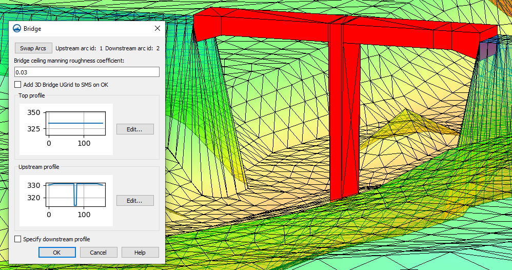
First, it’s important to know that SMS identifies the arc drawn first as the upstream side of the bridge. So the order in which the arcs are drawn affects the final bridge model. However, before the bridge is fully created, it’s possible to switch which side of the bridge is upstream using the Swap Arcs command in the Bridge dialog. Checking that the arcs are assigned to the correct side of the bridge can prevent errors later in the model.
When the bridge is created, it can be imported automatically into the model. So the bridge file is exported from SMS, but then SMS imports it automatically. To import the bridge automatically, select the Add 3D Bridge UGrid to SMS on OK option in the Bridge dialog. This eliminates the need to search for it then import it.

However, if the 3D bridge file is moved, it's important to keep in mind that two files were created by modeling the bridge: an XMUGRID file and a PRJ file that contains the projection for the UGrid. These files should be kept together.
Finally, modeling piers is sometimes an important part of modeling a 3D bridge. The top and underside of a 3D bridge are defined using XY Series Editors accessible in the Bridge dialog. When defining any elevation changes in the 3D bridge, the distance (x) values cannot be identical to each other. This means it’s impossible to create a precisely vertical slope using this tool. To approximate a vertical slope, first input distance values that are very close to each other (e.g. 79 and 80). Then, pair them with elevation values that reflect the change in elevation.
Use these tips in creating a 3D bridge in SMS 13.2 today!


