Using the Snap Preview Option
Having trouble with your boundary conditions or materials not aligning correctly with your mesh?
When a simulation runs in SMS, it takes all of the components—such as boundary conditions and materials—and aligns them with the 2D mesh or other geometry. When creating boundary conditions in the Map module for SRH-2D, ADCIRC, or other models that use simulation components, it can sometimes be difficult to know exactly where the boundary conditions will line up with the 2D mesh nodes.
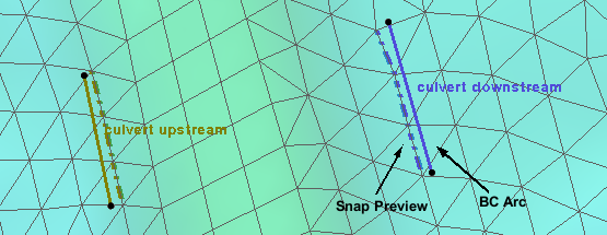
To help with this, the boundary conditions map coverage contains a display option to see how the map arcs and mesh nodes will line up: the Snap Preview option.
To use the Snap Preview option, do the following:
- Make certain the project contains a 2D mesh and a boundary conditions coverage that have been linked to a model simulation
- Open the Display Options dialog
- On the Map tab of the dialog, turn on the Snap Preview option
The Snap Preview option can also be turned on or off by using the Shift+Q shortcut key.
When the Snap Preview option has been turned on, a dashed line will be displayed along the element edge to show where the boundary condition arcs will match up with the mesh nodes. This is helpful in identifying if the placement of the boundary condition arcs is correct. Incorrect placement of boundary condition arcs can cause errors in the model run.

The Snap Preview option also works for other model coverages such as the SRH-2D materials coverage. This allows previewing how material assignments will match up with the mesh elements. Adjustments can then be made to the material polygons to correct any misalignments.
Using the Snap Preview option can significantly reduce frustration and prevent errors early on. Try using Snap Preview in your SMS projects today!


