Tips for Feature Stamping
By jcreer on December 11, 2019Have you ever needed to add an abutment, embankment, or other feature to your mesh and found it a struggle? We have some good news for you: SMS includes a function called Feature Stamping that is useful for this exact situation.
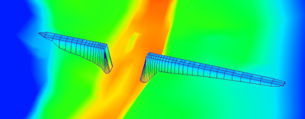
Feature stamping allows you to add man-made structures to an already created mesh by means of a stamping coverage.
You can find out more about this process in this wiki workflow.
There are, however, a few items to keep in mind when attempting to use the feature stamping tools. In this post, we’ll cover some of the most common, and how to troubleshoot them.
Make a High Quality Mesh
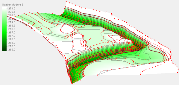
In order for feature stamping to be the most effective, it is necessary to enter them into a mesh that is already stable. Some items to look for include:
- Making sure the mesh has enough detail.
- Checking that the spacing between vertices isn’t too extreme in any portion.
- Making use of the Redistribute Vertices tool.
You can find much more about creating quality meshes on here our blog.
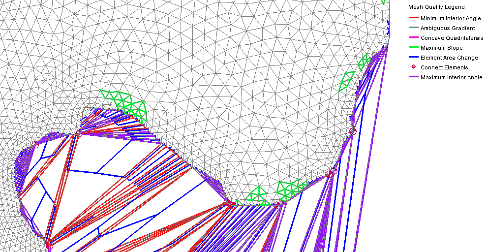
Avoid Disjointed Vertices
Disjointed vertices are points in the scatter that have not been connected to triangles or quadrilaterals in the mesh. Feature stamping will fail if there are any disjointed vertices in the mesh.
There are two options for fixing this:
- Find and delete all of the unconnected vertices.
- Re-triangulate the mesh.
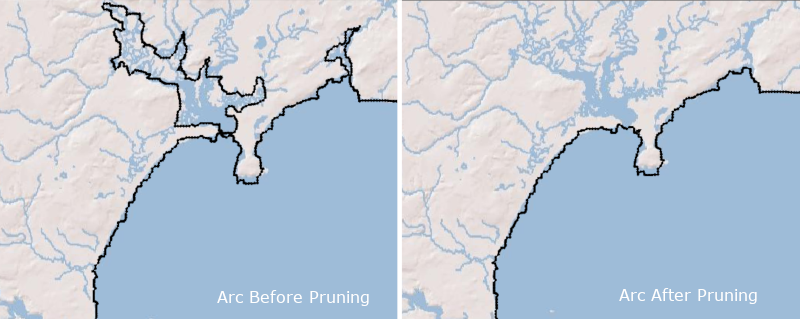
Keep the Stamping Features Short, Linear, and Independent
Feature stamping is usually linear, following a centerline.
If the structure is too large, or crosses over with other structures, it often has problems properly integrating with the mesh.
You can find examples here of when features are considered to be overlapping.
As long as your stamping features are reasonable in size and don’t interfere with each other, you should be able to successfully stamp your man-made features into the mesh.
Feature stamping is a very useful, but sometimes under-utilized, tool. Try out the feature stamping function in SMS today!