SMS

Viewing Mesh Quality and ARR Plots

After generating a mesh in SMS, we hope the mesh has everything you need for a project and nothing else needs to be done for the mesh. While this is often the case, some meshes do not generate as nicely as we would like. There might be small areas where solution variables change rapidly or spots with too many connecting elements.

Quality issues in a mesh can cause issues with the model results, so you can save a lot of time by reviewing the mesh quality before running your simulation.

SMS provide a number of tools for evaluating the mesh quality. Two of these tools are the Mesh Quality Display Options and ARR Plots.

Mesh Quality Display Options

After you’ve generated your mesh, one of the fastest ways to see the quality of the mesh is to turn on the Mesh Quality Options in the Display Options menu. To do this:

  1. Open the Display Options dialog
  2. Go to the Mesh tab and turn on the Mesh Quality option
  3. Click the Options button to change how the various mesh quality checks are displayed

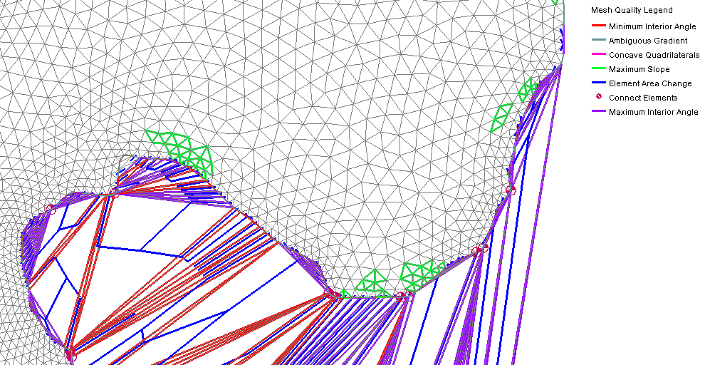
After turning on the mesh quality option, you will be able to more clearly see where there are potential quality issues. Each quality issues has its own color or symbol which is displayed in the legend. Looking over the mesh, it can become clear where there are potential issues.

ARR Plots

An Area Representation Region (ARR) plot can help you assess the overall quality of the mesh. To create an ARR plot:

  1. Select the mesh you want to review
  2. Open the Plot Wizard
  3. Select the ARR Mesh Quality option from the list on the left and click Finish

When the ARR Plot has been generated, you can use the plot to see the mesh quality.

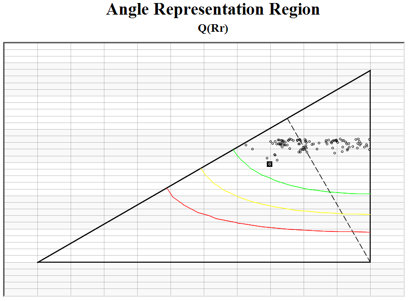
The plot has a point for each element. Points above the green line are good elements. Points below the red line are elements that should be reviewed and fixed. Points between the green and red line are elements that should be reviewed to see if they should be fixed.

Clicking on a point in the ARR plot will highlight the corresponding element on the mesh in the Graphics Window.

Try these options out in the SMS today!

Blog tags: 

Using an SRH-2D Restart File

Do you have an SRH-2D project that is going to take a long time to run? If you don't want your computer tied up for hours, or even days, an SRH-2D project can broken up into smaller model runs that build on each other. This is done by using a restart file or hot start file.

In SRH-2D, a restart file can be specified for the initial wet/dry condition of the simulation. The restart file must have been generated from a previous simulation run that used the same mesh. Several output options exist for creating restart files including: creating them at a regular interval, at a specified list of times, or a single restart file at the end of the simulation.

When SRH-2D does a model run, it creates a series of files for each time step. These restart files are named [casename]_RSTn.dat where n corresponds to the time index. The time series output index file is named [casename]_TSO.dat and holds a list that matches the restart files to a specific time step.

When a restart file is used as an initial conditions hot start file, the previously computed hydraulic conditions from the restart file will always be applied to the start time of a simulation.

To use a hot start condition, do the following:

  1. Run an SRH-2D simulation to completion.
  2. In the output files for the model run, locate the file ending with "TSO.dat" and open it in a text editor.
  3. In the TSO file, locate the time step where you want to use to start your next next simulation run.
  4. In you SMS project, duplicate your simulation.
  5. Open the SHR-2D Model Control dialog for your new simulation.
  6. In the Initial Conditions section, select the Restart File option.
  7. Press the Select button to browse to your restart file.

SRH-2D will now use the conditions from the restart file when you perform your next model run. Now that you know how to use a restart file for an initial condition in SRH-2D, try it in the Community Edition of SMS today!

Blog tags: 

Troubleshooting Errors in SRH-2D

It happens. You‘ve finished building your SRH-2D model in SMS and you launch the model run. Then, to your dismay, SRH-2D stops running and gives you an error.

It’s not fair. You did everything correct and entered all the correct parameters. SRH-2D should be running and giving you its valuable results. But instead you have an error message.

Don’t panic.

While it is discouraging for SRH-2D to not complete when you launch the model run, it is only telling you that a key bit of data is missing for it to give you valid results. The error code will help you locate that data or fix an inconsistency.

But how do you use the error code to find what needs to be fixed? And shouldn’t the SMS model checker have found it before SRH-2D started?

The SMS model checker verifies all the data needed to run SRH-2D is present and looks for errors in the SMS project such as dangling arcs, numbering issues, or missing components. It does not validate the data. Once the SMS model checker has finished, SRH-2D performs its own checks during the model run.

When SRH-2D gives you an error, you’ll need to record the error number. Errors are shown in the model wrapper. Clicking on the Pre-SRH-2D button will show if there are errors during the pre-processor run. Clicking the SRH-2D button will show errors during the model run.

Once you know what the error is, you can look up the list of SRH-2D errors on the XMSwiki here. The article contains a list of known errors along with guidance on how to fix them.

If you were unable to record the error from the model wrapper, don’t worry. You can still see this information by reviewing two of the files generated by SRH-2D during every model run. These files will be named [projectname].OUT.dat and [projectname].DIA.dat files.

To use these files:

  1. Locate the files in the model run directory with your project file.
  2. Open the *.OUT.dat or *.DIA.dat files using a text editor such as Notepad.
  3. Look through the text file to locate the error code.
  4. Go to the SRH-2D error page to find the solution.
  5. Make the needed change(s) to your project and run SRH-2D again.

Typical solutions to SRH-2D model run errors might involve adjusting some data inputs or making minor reconfigurations to boundary conditions or structures. While making these changes to a project can sometimes be frustrating and tedious, getting an accurate end result will make it all worthwhile.

This is a great troubleshooting process you can use to create many successful SRH-2D model runs. If you haven’t already made use of SRH-2D, feel free to explore it in the Community Edition of SMS.

Blog tags: 

Using Snapping in SMS

In many projects, you might find a need for nodes or vertices to line up exactly. You can achieve this by using the Snapping feature in SMS. Snapping nodes to arcs can be accomplished two ways in SMS: by cleaning and by using the snapping crosshairs. In some cases, two arcs might need to be very close to each other but not snapped to the same nodes or vertices on a mesh. This post will discuss how all of this works.

Clean Option

The Clean option allows any two nodes on the same coverage to be "snapped" together To snap two nodes on the same coverage:

  1. Select the desired nodes.
  2. Select the Clean... command from the Feature Objects menu.
  3. In the Clean Options dialog, turn on Snap selected nodes.
  4. Select the desired node as the snapping point.

The nodes will be merged into one node at the desired location.

Nodes and vertices can also be snapped using a tolerance value. This will snap all nodes in the coverage to be within the tolerance.

  1. Select the Clean... command from the Feature Objects menu.
  2. In the Clean Options dialog, turn on Snap nodes and vertices.
  3. Set the Tolerance level.

The tolerance units are the same as those set in the projection. This method may cause vertices to be redistributed along some arcs, so it should used carefully.

Snapping Feature

If Snapping is turned on the Map tab in the Preferences dialog (see image below), red crosshairs (see image below) will appear when creating an arc and the mouse moves near an existing node or vertex. This indicates that the node or vertex will snap to the existing node or vertex in the coverage. If two vertices snap, they turn into a single node. Snapping can be turned on and off when in the Map module by pressing "S" on the keyboard.

Snapping Across Multiple Coverages

To snap across multiple coverages, Inactive coverages must be turned on in the Display Options dialog. This prevents nodes or vertices from appearing to be snapped when they are not (see the images below). The first shows what appears to be two vertices that are snapped. The second shows a zoomed view showing they are not actually snapped.

Snapping can also occur between a coverage and a geometry such as a mesh or a grid.

Nodes That Should Not Be Snapped

Keep in mind that if two boundary arcs are close to the same node(s) on the mesh or grid, a simulation may snap them to the same node(s) within the simulation, which may cause errors. This can be fixed by either refining the mesh or grid so there are more nodes to use, or by moving one or more of the arcs slightly.

Try using the snapping feature today in the Community Edition of SMS.

Blog tags: 

Pages