Converting a 3D Dataset to a 2D Dataset
By aquaveo on August 21, 2019It sometimes happen where you have a fully developed 3D model in GMS and need to transfer a dataset from the 3D model to a 2D model. GMS provides a way to convert a dataset on a 3D grid to a 2D grid. From there the dataset can be exported as 2D data for use in a 2D model.
To acquire a 2D dataset from a 3D dataset, you need the following:
- 3D grid
- 2D grid
- 3D dataset
To convert a 3D dataset to a 2D dataset, do the following:
- In the Project Explorer, select a dataset under a 3D Grid.
- Use the Grid menu to select the 3D Data → 2D Data command.
- Select option in the 3D Dataset → 2D Dataset dialog.
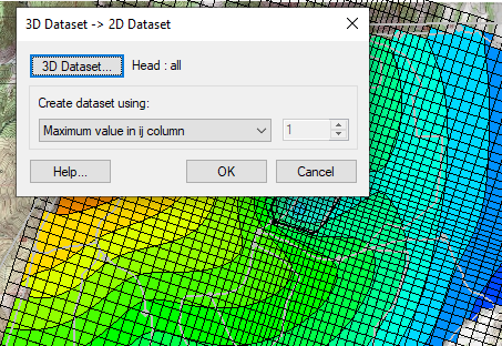
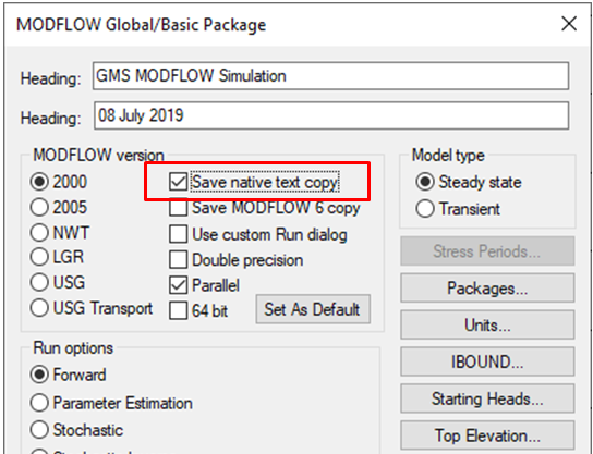
The 3D Dataset → 2D Dataset dialog allows choosing which dataset to converted. By default, the dialog will use whichever 3D dataset is active in the Project Explorer. If another dataset is desired, from a MODFLOW simulation for example, you can make the change in the dialog..
The dialog also allows creating the new 2D dataset using one of the following parameters:
- Maximum value in ij column
- Minimum value in ij column
- Average value in ij column
- Sum of values in ij column
- Highest active value in ij column
- Value from k layer
K represents the layer number with 1 being the surface layer, and J and I representing the x and y locations of a cell (or column of cells) in the grid.
Keep in mind that one of the grids could be covering the other so if you want to observe specific data, you may need to turn off other data.
Additional additional information about converting 3D grids to other data can be found on our wiki.
Try out converting 3D datasets to 2D datasets in GMS today!