Tips for Building a CE-QAUL-W2 Model
By aquaveo on February 9, 2022Are you building a CE-QUAL-W2 model in WMS? CE-QUAL-W2 is a 2D laterally averaged hydrodynamic and water quality model. It can model vertical variance, eutrophication, seasonal turnover, algal blooms, etc. if incoming pollutants are known. Setting up a CE-QUAL-W2 simulation involves dividing the reservoir into segments, branches, and layers and determining the geometric properties of each segment, branch, and layer.
When building a CE-QUAL-W2 model, keep the following in mind:
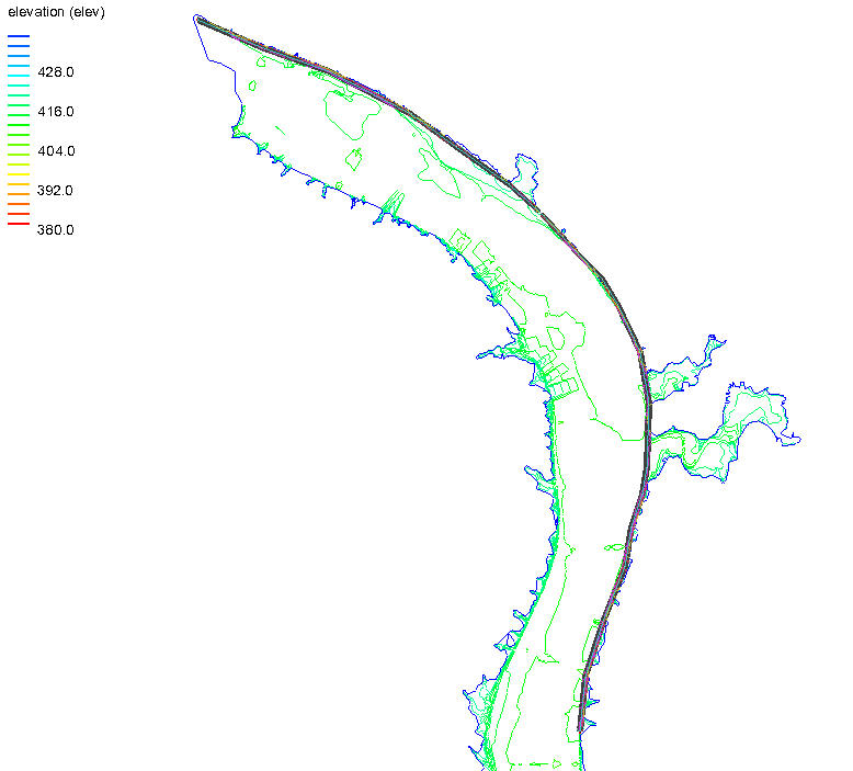
- Make certain that the site you have chosen is appropriate for the CE-QUAL-W2 numeric model. It is best applied to long and narrow water bodies that have longitudinal and vertical water quality gradients. The further your site location deviates from a long and narrow water body, the less ideal it is to CE-QUAL-W2.
- When setting up branches, you may need to remove smaller branches and offshoots. This may particularly be the case if you used the TIN Boundaries to Features command. Using this command can end up including small branches and offshoots that are unnecessary for the final model. Each branch should be examined and judgment exercised on the importance of including it in the model. To remove the unnecessary branches, smooth out the bounding polygon.
- Before smoothing out a bounding polygon, it is recommended that you duplicate the original map coverage in order to retain the original coverage data. Then use the map tools to smooth out the bounding polygon for the coverage that will be included in the model. Remove any extra coverages when you finish smoothing the bounding polygon.
- Verify that all segments are measured and assigned correctly. This is done by double-clicking on any segment in the segment coverage and using the Polygon Segment Attributes dialog to review each of the segments. Either enter values for segments that are missing attributes or remove the segment.
- Review branches through the Polygon Branch Attributes dialog. This is accessed by double-clicking on any branch in the branch coverage. Make certain to enter values for all branches.
Using the tips above can help assure that your CE-QUAL-W2 model executes correctly. For additional support, contact our technical support staff. Try out CE-QUAL_W2 in WMS today!