Reviewing Aquaveo Licensing Information
By aquaveo on January 6, 2021In order for your Aquaveo software (GMS, SMS, WMS) to function correctly, it must be licensed correctly. It also must have all the correct components licensed for you to run the packages you have purchased. When you encounter an issue with your license, you can review your license information in order to know what to do.
To see your license information, do the following:
- Go to the Help menu and select the Register command.
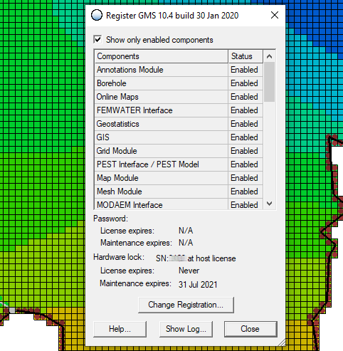
In the register dialog you will see your license information, including your license number, license expiration date, and maintenance expiration date. The license number will often be needed when contacting Aquaveo for support. The license expiration date shows when your license will expire, after which you will no longer be able to use the software without a new license. The maintenance expiration date is different from the license expiration date. The maintenance expiration date is the date after which you will no longer be able to receive technical support or access newer versions of the software including bug fixes.
In the register dialog you will also see a list of components enabled with your license. Components include numerical models, interface options, and tools that can be purchased with a license for our software. Review this list to make certain that you have all of the components you expect to find with your license. There is an option at the top of the dialog that can be turned off to see components that have not been enabled.
Often when a component is not enabled, this is because that component was not part of the license package that you purchased. Components can be purchased as part of a license package or purchased individually. To add a component to your license, contact our sales team at: sales@aquaveo.com
If you find that a component is not enabled that you believe should be enabled, contact Aquaveo’s licensing team at: licensing@aquaveo.com
If you are experiencing trouble registering your license or accessing a component of your license, contact our technical support team at: support@aquaveo.com